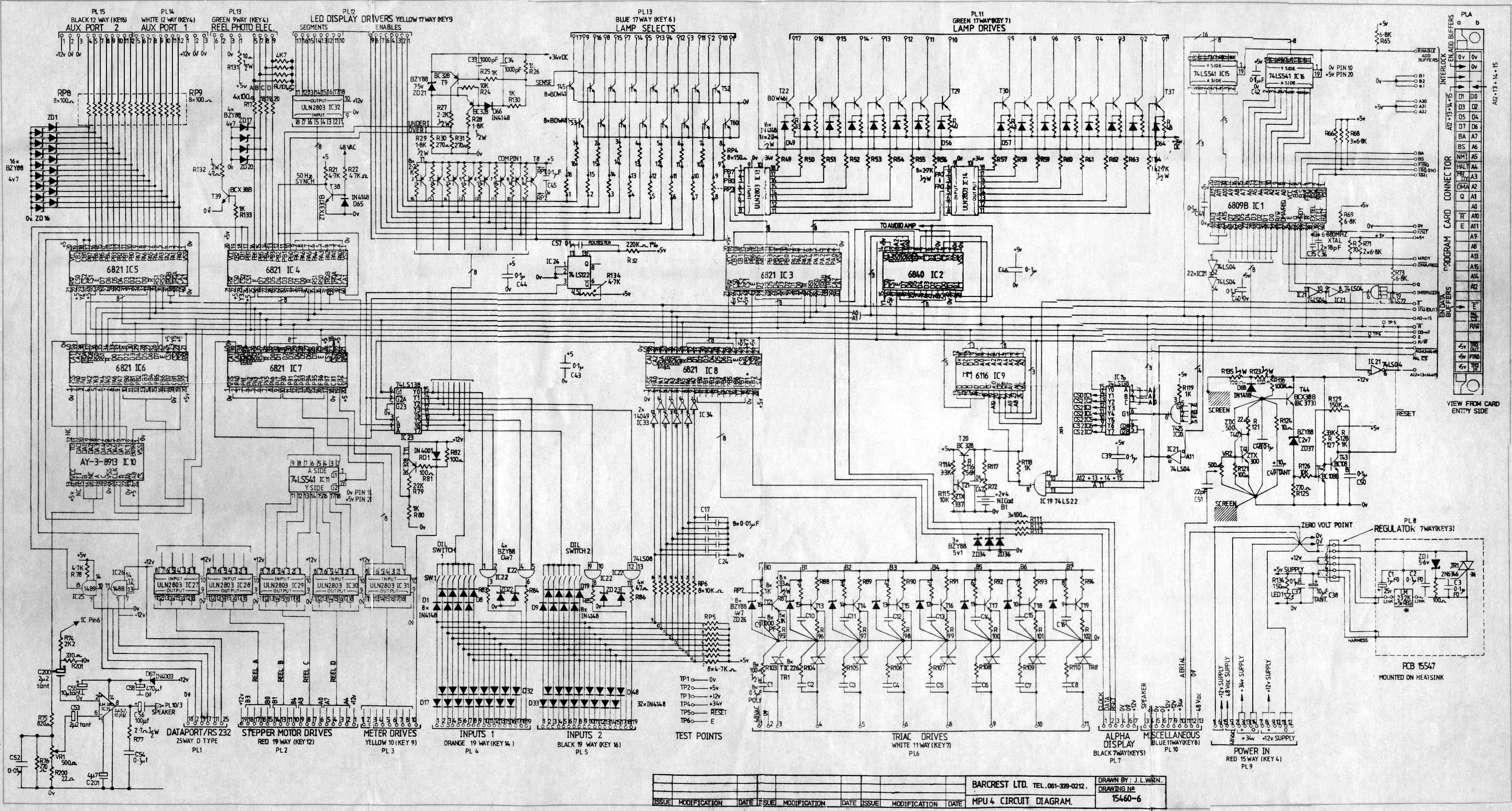
Repairing an MPU4 board is a logical process of elimination. You start at the beginning and diagnose the fault. When you first look at the PCB above you will not have the faintest clue where to begin, but with a little patience and time you will begin to understand what the different parts of the MPU do and how you can repair a fault. There are 2 ways to repair a board. The first is to roughly know which part of the board is at fault and change the part or to diagnose the fault using a multi-meter and/or logic probe or a combination of the two.
Everyone has their own preference for soldering and parts. I would say use a temperature controlled iron with a point tip at 400 degrees C. Use lead solder not that lead-free stuff. Get some good Servisol solder-mop for soaking up solder. Some good turned pin strips for your ICs. You need a good light source, a fibre glass pencil with refills. That’s probably enough
to get started. Parts can be obtained from ebay and various other suppliers.
Let’s not beat about the bush, you just need to know which part to replace and where to get it? I’m with you on that one.
I’ve created a flow chart to get you off the mark.
Download faulting finding flow chart
Repair log 3 - Dead short MOD4
Repair log 4 - Lamp fault MOD 2
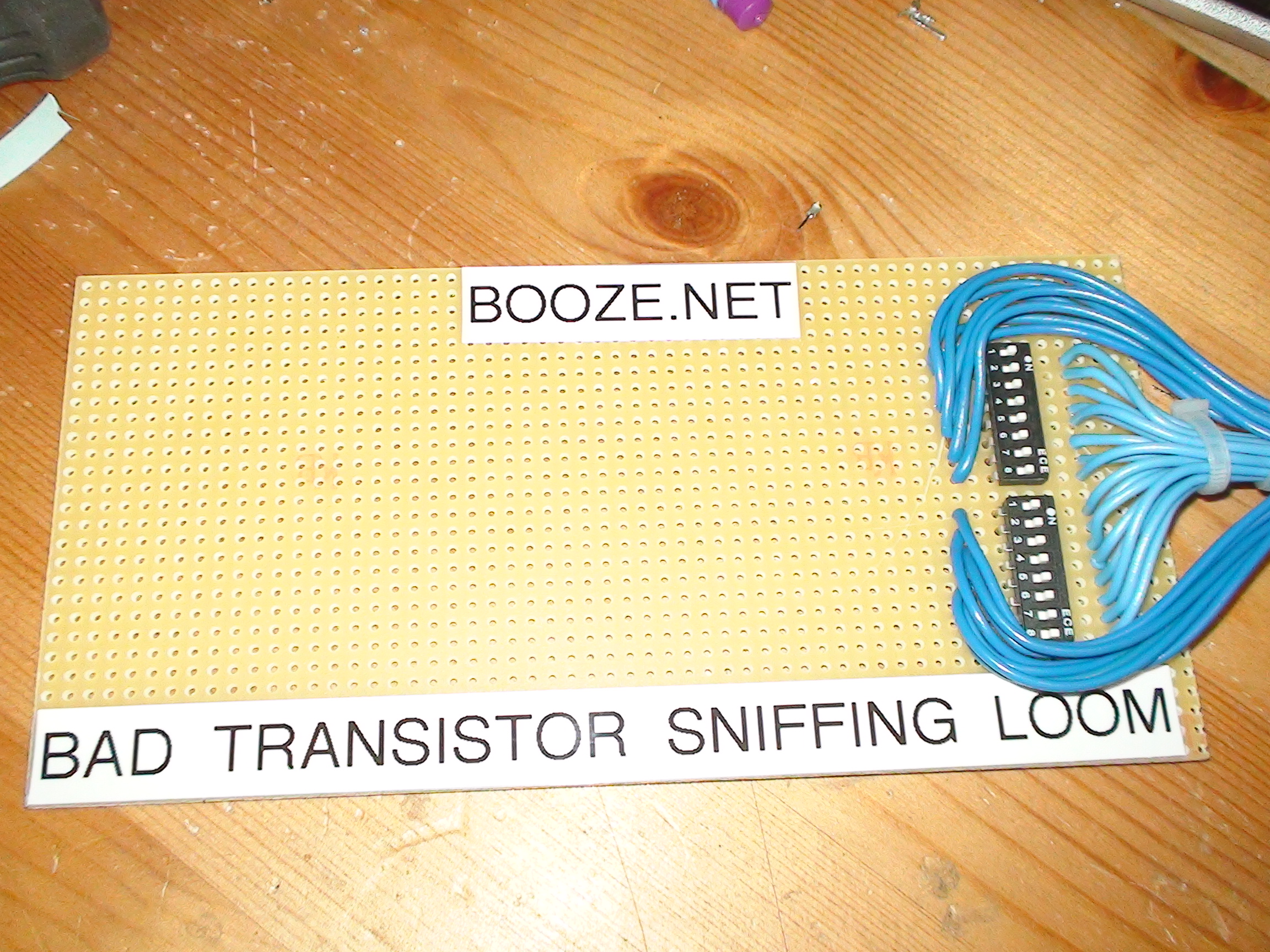
Sniff out that bad transistor with the booze.net bad transistor sniffing out loom. Just get yourself some PCB strip board from maplins and some 8 switch dils and cut the blue loom in half. Wire each through each bank of the DIL switch. You can then switch each transistor on and off as required. No more time wasting with the meter, you know which one is bad the moment it alarms. Green plug is next and the triacs also. DIL switches are cheap and very neat. Also nice to PCB mount, remember to cut the tracks horizontally across the switch or you’ll be forever closed)
The buzz from fixing your own fruit machine cannot be over stated. It’s like nothing else!